Swapping the printer's electronics: the plan, and a hole in the bed
Marlin 2.0, an Arduino Due with a RuRamps4D hanging on strings, and a PEI sheet melted right in the centre.
All the parts I need to upgrade the hardware platform of the 3D printer have finally reached me, so I finally started looking into how to do it.
In essence, all of the firmware and the control electronics have to be replaced. Among the problems: I have nowhere to mount the new RuRamps4D on the printer, for example. The old RAMPS was simply attached to the side wall, and this thing is 3 times bigger and there is just nowhere to put it. And if I put it on the desk next to the printer, I need to print a case for it and hope the wires reach. And there are a million details like that. So I will solve this upgrade in parts, and report on my progress here.
The plan:
Rebuild the firmware from Marlin 1.1 to Marlin 2.0. Marlin 2.0 got support for ARM boards, including the Arduino Due + RuRamps4D sandwich, but the configuration and the code changed completely. It became clearer, more modular and cleaner in general.
Disconnect the old sandwich (preferably after labelling which wires went where).
Move the old drivers onto the new sandwich and connect the new sandwich with a Marlin 2 firmware built for Arm. Connect it in a minimal configuration (bed, nozzle, motors, power control) and do a test print. The catch is that, judging by what I found on the internet, Chinese copies of the Arduino Due (my case) do not work with the RuRamps4D out of the box, and something has to be changed on the board itself.
Connect the rest: display, laser, part cooling. Make sure laser engraving works.
Switch to the new TMC2130 drivers. The catch is that these drivers are smarter than me and have to be configured somehow, and since I ordered the boards with them from China, SPI control is blocked by default. To fix that, you have to desolder a very small resistor from the board and break one circuit. And you already know how I am with soldering.
Print a separate desktop case for the sandwich (maybe hide the raspberry pi in there too and move the display over?)
Go completely overboard and add a USB Mass Storage Class emulator for the memory card to Marlin 2.0, to copy files straight onto the printer's SD card over Samba from the RPi.
Think about buying a Nextion display for the printer to replace the usual Smart Graphics Controller. (Pretty, colour, and a touchscreen too, lovely!)
So far I have done point 1, and even there I managed to mess up a little (surprisingly little!). I carried over all the changes in the settings carefully, flashed it, everything turned on at the first attempt. I tried a test print and realised that homing on the Z axis goes 2 mm into the bed. Since I was doing it with the nozzle already heated, my PEI sheet melted through right in the centre, so it will have to be replaced after the rework. It turned out that after such a big update you have to reset the EEPROM (where all the settings are stored). And I even knew that once, but forgot :(
Once the test print on the old sandwich with the new firmware finishes, I will go on with the plan.
Two days later
The printer saga continues. I took the old stuff apart and almost assembled the new. Point by point:
In the minimal variant printing works. I printed a test cube with the speed cranked up 3 times compared to the usual.
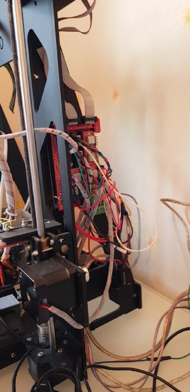
The only place all the wires reach is the same place where the board used to hang. One of the holes in the frame (bottom right) matched the board, so the decision was to mount it there again. The other holes do not match, so for now the board hangs on strings 😁 Really I need to print a case for this sandwich and mount that.
Difficulties came up with power control. I use a converted ATX power supply, and it has such a thing as power control. In essence there are 5V that are always on, and a signal wire (PS_ON) which, when shorted to ground, turns on all the other lines (and the fan in the power supply itself, yep). Those 5V power the Raspberry Pi that runs the print server, and the Arduino is connected to it over USB.
Now watch my hands. Thanks to USB power the Arduino is always on, and it can set the pin PS_ON is connected to to 0 or 1, and that way turn on or cut power to the whole 12V part, the motors and so on. And this even works.
However, a small display and an SD card are also connected to the Arduino, and they need 5V. And since the Due has all logic levels at 3.3V, with the power off the card and the display do not work, and it is not clear yet how to get power to them.
The laser. I have a 2.5W diode laser with two cables: 12V power and 5V TTL. I got completely confused about which of these can be driven with PWM and which is simply switched on and off, but that is not the point yet. If the 5V is the PWM one, where do I get it? I have 12V, and I can limit the maximum duty cycle to 41% in software, but that limits my burn resolution a lot. As an option, the Due seems to have a proper 10-bit PWM, so I could rewrite the firmware a bit and bring the resolution back. But for now this junk at least has to be connected so that it works.
I have not got round to installing the new drivers yet, but I googled and found that on my units SPI control does seem to be blocked, and to remove the block you have to desolder a veeery small resistor. And the soldering iron tip seems to be completely done for.
P.S. I searched the internet for examples of implementing usb mass storage on the chip in the arduino due and did not find any. So I will hardly implement the printer emulating a flash drive. And given that everything is mounted almost the same way as before, the Nextion seems to be going the same way.
A week after that
I have not touched the printer since, except that I understood that the laser has to be powered from 12V and PWM-ed on the 5V TTL. I still have no idea what to do about power for the display and SD card. I asked on the forum of the ruramps4d's author, and I think they are waiting for me to answer with a diagram of how I have all this connected.